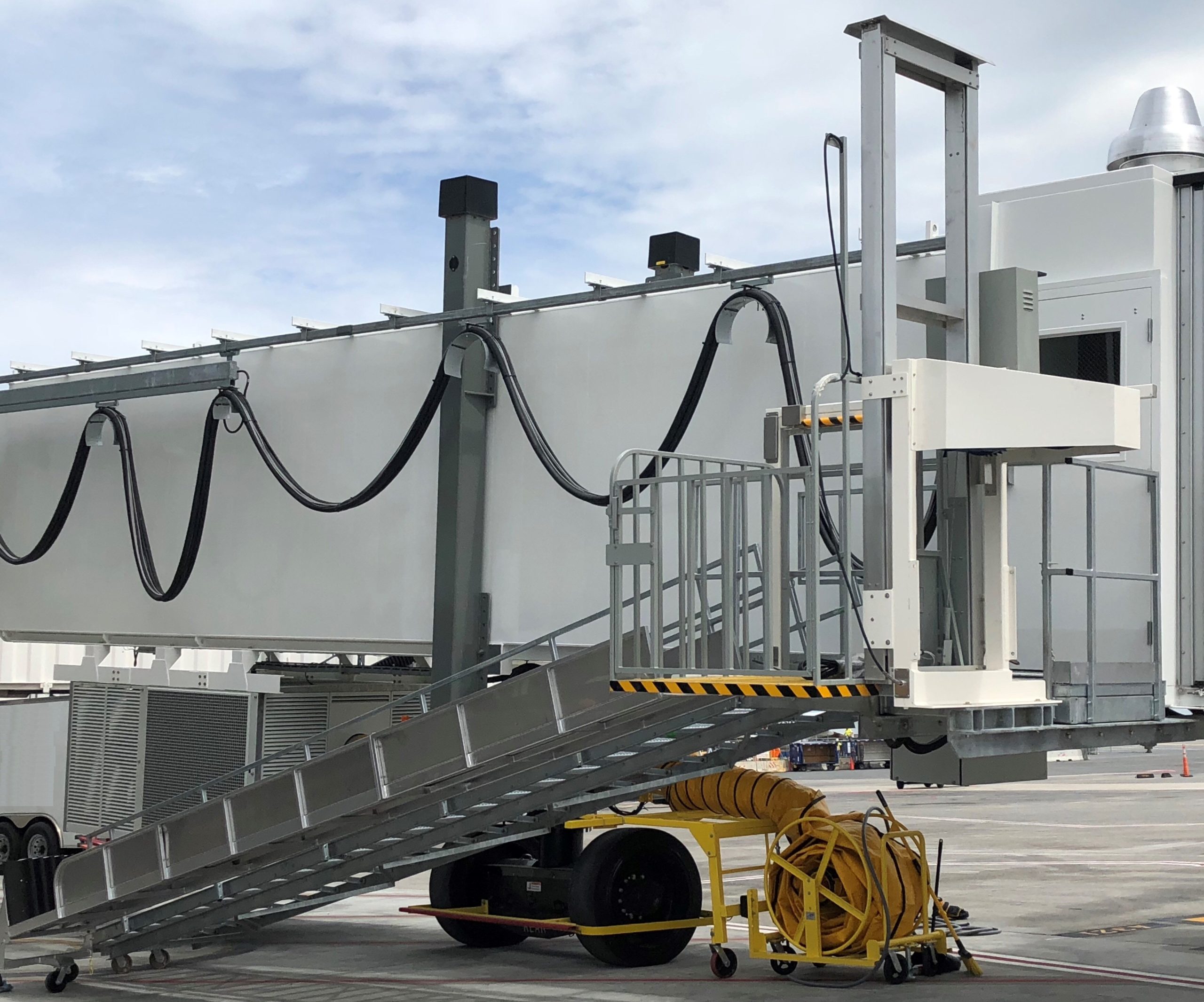
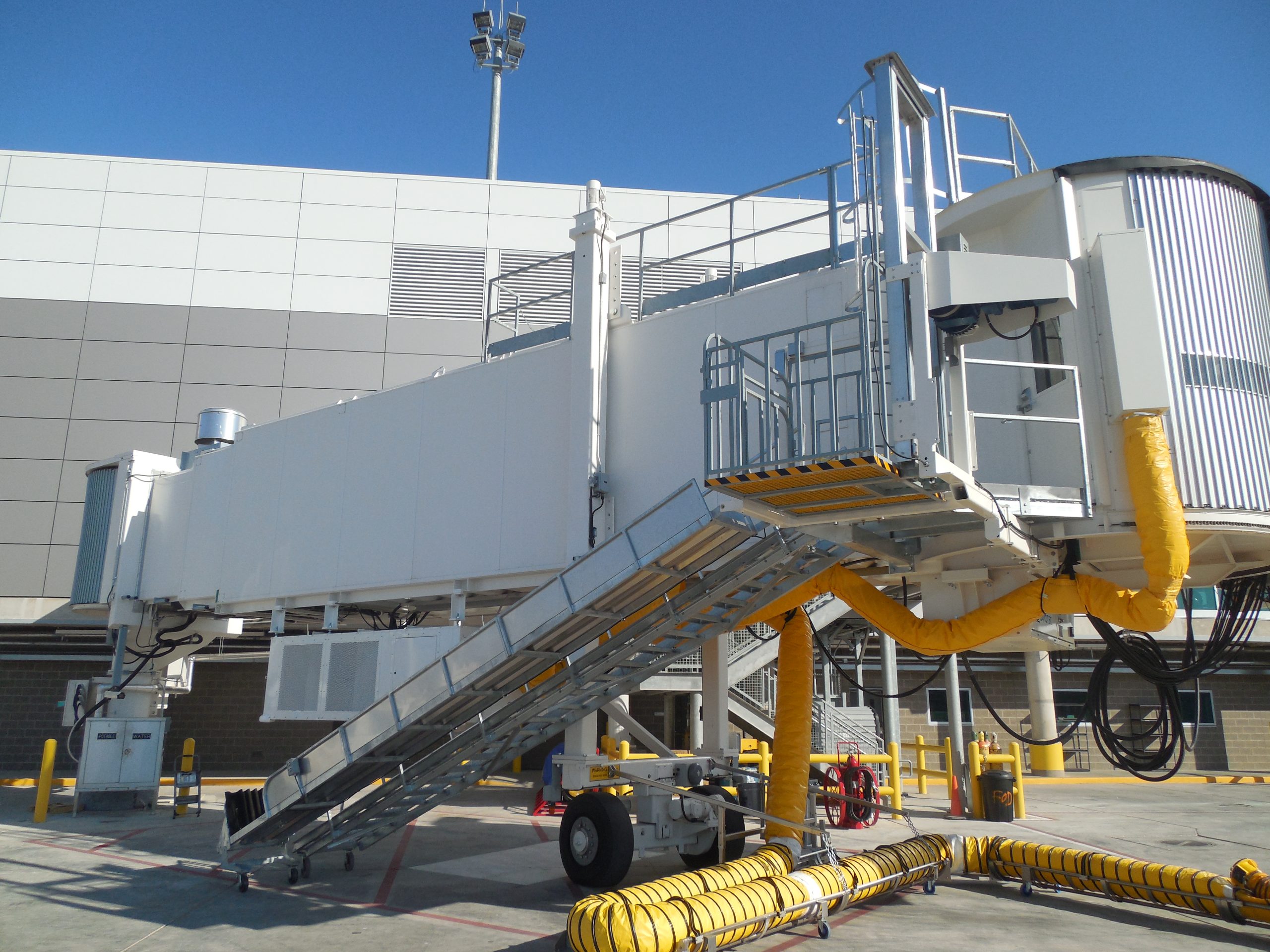
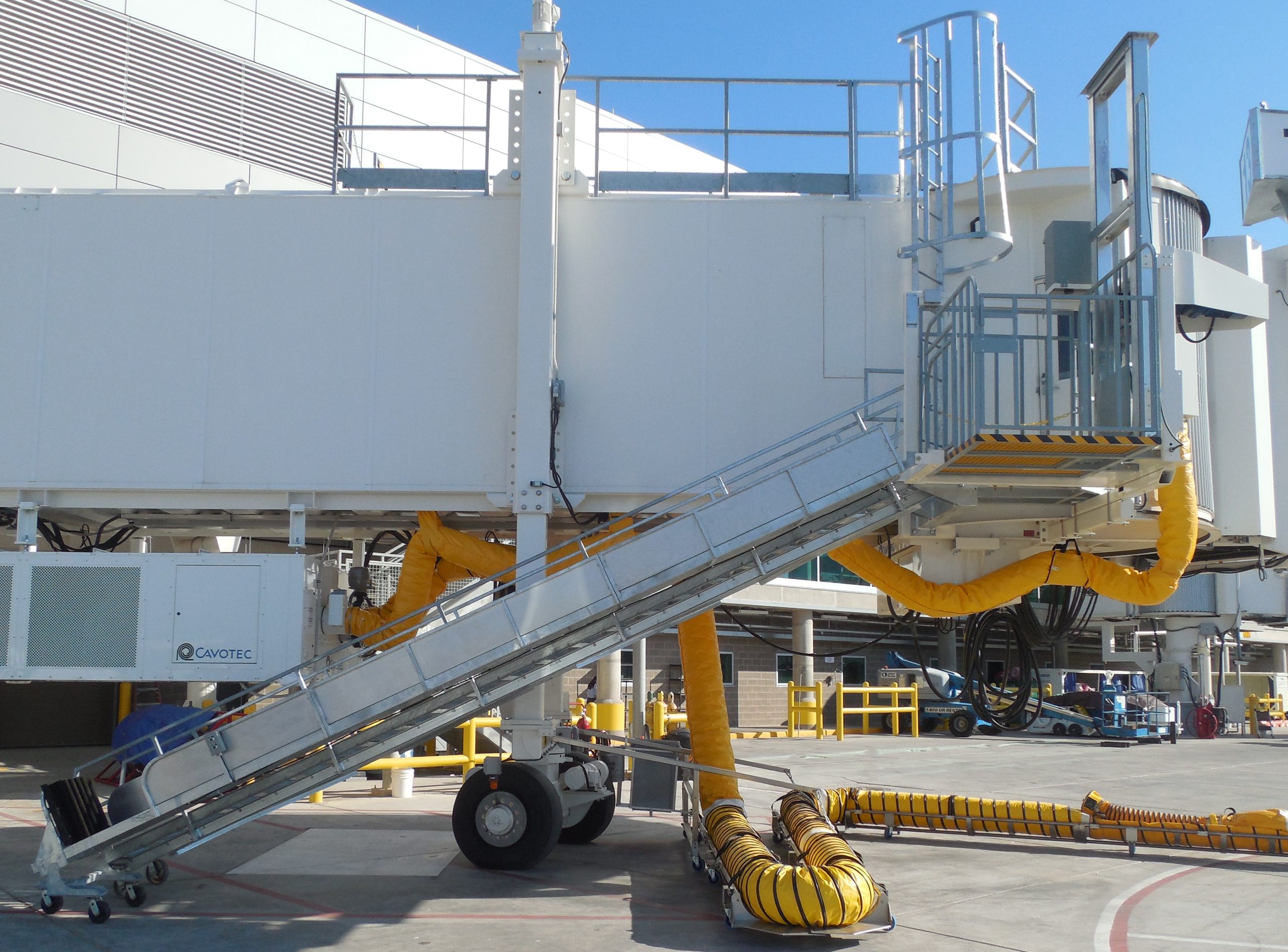
Nova Baggage/Wheelchair Lift
The Baggage Lift is a ETL Listed bridge mounted wheelchair and luggage lift that is capable of moving NON Live loads up to 500 lbs. from the bridge level to the ground for loading and unloading. The lift meets ASME B30 standards that is driven with a motor winch system with 3/16″ stainless steel cables. The Nova Baggage Lift has been approved for installation by both of the major bridge suppliers in the US and Europe. JBT and ThyssenKrupp.
Weight: 1200 pounds
Rated Lifting Capacity: 500 pounds
Electrical Power Requirements: 110 VAC maximum current draw 10 amps. The lift is ETL listed.
Width: 60″ Length: 101″ Height: 121″
Height of Sliding Door opening: 52″
Width of Sliding Door opening: 50″
Capable Travel for Wide Body Aircraft Height
- The Nova Baggage Lift (NBL) is an electrical/mechanical, bridge mounted vertical reciprocating conveyor for Lifting/lowering cargo associated with the aircraft passenger industry. It is not certified for lifting live loads, Neither people nor pets. The NBL Is approved for installation on ThyssenKrupp and JBT Passenger Boarding Bridges.
- A sliding gate made of 1” square aluminum tubing is attached to a channel on the landing side of the NBL. UHMW slides provide the bearing surface to facilitate a smooth and stable way for the gate to open and Close. There is also a safety latch associated with this gate so that when the lift car is lowered, the gate cannot open.
- The NBL lift car travels vertically at the rate of 45 feet per minute. The rated load capacity of the lift car is 500 pounds. The redundancy factor for the lift car is an engineered/tested minimum of 4 to 1 (2000 pounds). The lift car floor size is 4’ long and 4.5’ wide from the landing outboard.
- The car has two aluminum tube containment side walls, each being 42” high. A gate to access the Nova Slide isincorporated in the sidewall closest to the Nova Slide.
- A safety chain crosses the opening closest to the bridge. Three eyes are provided for the chain. One eye affixes thechain to the car, one eye allows the chain to be stretched across the opening and the other allows the chain end snap to be attached to the car out of the way of the opening.
- An aluminum square tube gate is attached to the opening on the side furthest from the PBB. A piano type hinge affixesthe gate to the lift car. A simple latch bar locks the gate in place.
- The floor of the lift car has inset panels of fiberglass grating such as that manufactured by Fibergrate Corporation ofDallas Texas. The material is extremely durable and has an excellent nonskid surface.
- A 28” width (approximately) slide entrance gate is located in the lift car side next to the Nova Slide to allow egress to the Nova Slide from the lift car.
- The NBL chassis is a tubular steel (A36) welded structure. The minimum thickness of any steel used on the NBL is 11 gage (3/16”). The chassis provides for mounting points to attach the NBL to the bridge, house the various mast components, electrical components and attachment points for affixing a Nova Slide U.S. Patent 6390757. Additionally, the chassis provides mounting support for the sliding landing gate located between the bridge landing and the NBL.
- The lift car mast is designed to provide a smooth telescoping method of stabilizing the lift car in its vertical travels. Additionally, it houses patent pending emergency break actuators that immediately stop the descent of the lift-car/mast in the event of a broken lift cable.
- The fixed portion of the mast, attached to the chassis consists of extruded 6061-T6 aluminum “C” Channel, 4” web x 2” flange x 10’length. These two section are mounted perpendicularly to the chassis base.
- The center telescoping section is a custom extruded aluminum “I” beam with a 3.5” flange and 5” web, 10’ overall length.
- The inner mast sections are of the same 4” x 2” x 10’length “C” Channels. Spacing is determined by an upper spreader and the lift car members.
- The mast members glide on custom UHMW wheels. There are two sizes of wheels used to correspond to the width of the track that they glide on (approximately 3.4” and 4.5” diameter). Each roller is supported in position with 1” diameter shaft. Owing to the low RPM of the wheel (less than 15 RPM) there is no detectable heat buildup and no lubrication of the wheels is ever needed.